A lot of rain is falling onto flat roofs, and from the dawning day of the flat roof, it always has done.
So, the question is when dealing with the problem of flat roof drainage, why do some people still get it wrong? What do we need to consider when getting an efficient drainage system with the right number of rainwater outlets in flat roof design?
The logic is quite simple. Encourage the water to find its way to adequate points of drainage and let it discharge through the pipework to carry it to ground level drainage.
Fortunately, most designers and constructors do get it right. But our experience at IKO Polymeric sees enough evidence to suggest that some don’t fully understand the requirements.
Rainfall onto flat roofs needs to be correctly managed to protect the structure against ingress of water. This should be addressed in two ways.
Firstly, the roof must be designed to achieve adequate falls, ensuring water will move to the designated low points.
Secondly, but no less important, the roof needs enough number of correctly sized outlets to collect and discharge the surface water.
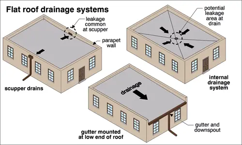
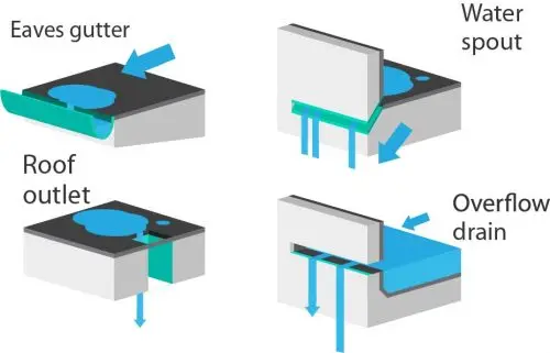
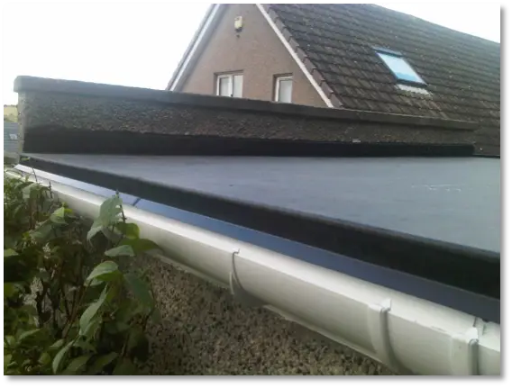
Rectangular shaped roofs are straight forward to design, with many adopting the logic of getting the water to the edges and then off the side of the roof. This can be achieved by full length external guttering or typically, via chutes at predetermined positions.
One of the benefits of this method is the waterproofing is not being penetrated and pipework is not routed through the building interior.
Some people dislike seeing down-pipes and whatever else is used to transport the water to the ground level; and therefore, opt to use an “Internal” option.
Roofs come in many shapes and sizes from simple rectangular designs to complex shapes. Some have steps, daylight systems, mechanical and electrical plant and other obstructions such as lift overruns, all of which, can restrict the free flow of surface rainwater.
In these cases, the design of workable falls can be complex. On large roof areas, having fewer outlets may cause a further design issue. As an example, if the run of fall from a notional high point to a point of drainage is 20 meters, then a minimal fall of 1:80 will see the roof level rise by 250mm.
Once the roof levels are designed and approved, the selection of the rainwater outlets can be reviewed.
Which type of rainwater outlet can prove beneficial to the design and performance of roof drainage and ultimately, the building? Flat roof drainage falls into 2 main categories, gravity drainage and syphonic drainage.
Syphonic drainage was developed and first used in Scandinavia in the earlier 1970’s and first used in the UK in the 1980’s.
There were initial problems with some of the earlier installations due to a misunderstanding of the system by inexperienced companies. Today there is a core group of companies who specialises in this field.
Syphonic system use reduced bore pipework and fewer outlets but requires consistent levels of a build-up of water level to instigate the syphoning process.
Further benefits of syphonic drainage also include keeping the pipework horizontal at high levels. It also reduces underground drainage requirements. It is best suited to large warehouse style buildings and aircraft hangars as well as large superstores.
It can be used on large school buildings but can be a noise nuisance. It can also vibrate in use so needs to be secured firmly.
Mostly roofs are equipped with gravity drainage. They can also comprise of preformed type units that have a pipe spigot fitted to a flat “plate”. This sits at, or preferably, below the level of the waterproofing or engineered units that offer increased flow rates and can be formed of thermally efficient polyurethane.
Both will normally sleeve inside down-pipes. Additionally, chutes can be provided to feed through vertically with the rainfall run off, discharging into external hopper head systems.
What is going to provide the performance needed and can it be done cost effectively?
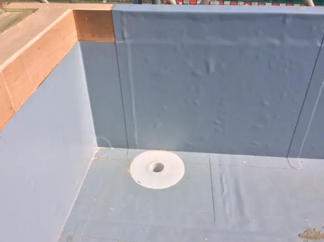
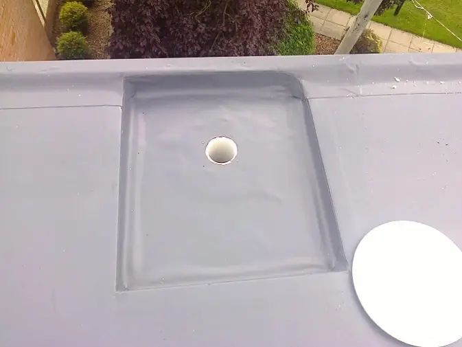
As an example, what follows is a comparison in performance of gravity drainage options.
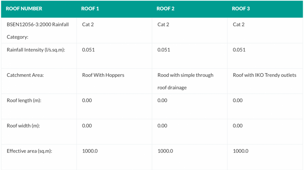
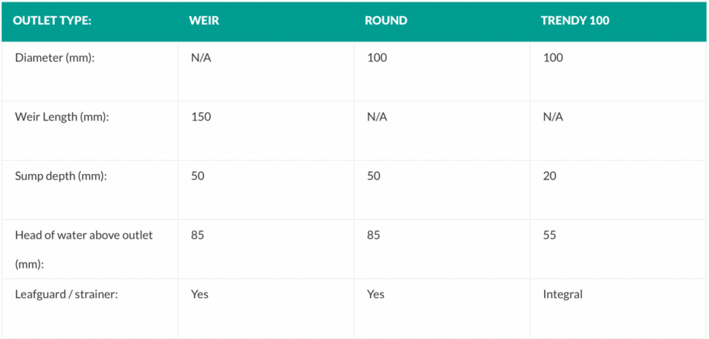
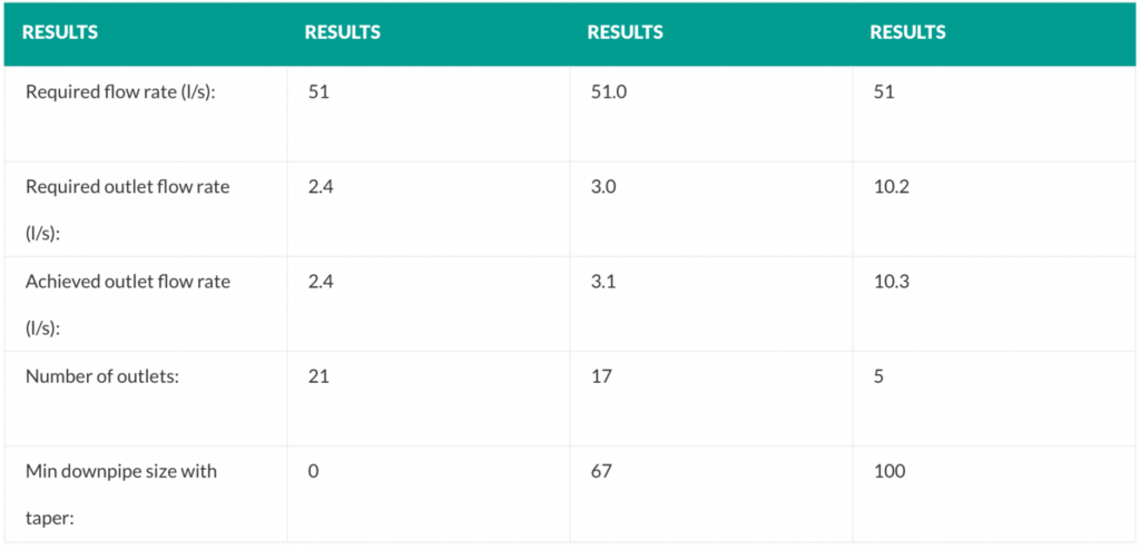
A freestanding roof of 1,000m² based in Chesterfield will produce a flow rate of 51 l/s and with 150mm wide rectangular weir outlets. External hopper heads in the region require 21 outlets.
This figure includes for a 50mm sump to aid the flow rate. It is worth pointing out that horizontal circular outlets are less efficient as the widest portion is midway up the opening. This could double the number of outlets required.
Taking the same roof but using basic 100mm diameter “through the roof” gravity drainage would see a requirement of 17 outlets. Again, the calculation has been made utilising a sump with a depth of 50mm.
Compared to horizontal outlets, the “through the roof” outlets not only reduce the numbers of outlets required but also the associated pipework and labour. Both the above options were based on economic rainwater goods.
Spending more money on the individual components can save costs during the construction and installation stages.
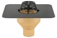
As well as simple economic rainwater outlets, IKO Polymeric also offers IKO Trendy outlets, a range of high-performance outlets with much higher flow rate. IKO Trendy rainwater outlets are available in four diameters: 70mm, 90mm, 100mm and 125mm.
Using the same dimensioned roof in the same location, the introduction of the 100mm IKO Trendy outlets reduces the number of required outlets to 5.
In this case, the sump was only 20mm as the rainwater outlet was performing at peak levels. The advantage is they have a much more efficient drainage system, utilising the engineered components.
So, can spending more save costs? Let’s look at the example that required 17 outlets. This equates to = £A x 17, whereby the comparison with the Trendy option (£B x 5) works out to be £A x 17 less 20%.
As mentioned before, this is just for the outlets and not all the associated costs of addition pipework and labour that the higher number would command.
The calculation follows good practice and makes an allowance that leaf guards are fitted. The results of the sample drainage calculation are included below.
